
Common Types of Electric Circuit Boards Used in Electronics
The circuit board is a key component in modern electronic devices, and understanding the basics of its design, construction and components can help you make better use of them. The circuit board consists of electrical pathways, typically made of copper, that allow current to travel between different parts of the device. These pathways are carefully designed to maximize conductivity and minimize resistance, making them essential for proper operation of the circuit board. These pathways are connected by various electronic components, such as transistors and integrated circuits, that either amplify or switch electronic signals. They are also used in conjunction with capacitors and inductors to create circuits such as oscillators and filters.
Conductive pathways, or copper tracks, are etched onto the surface of a electric circuit board. This etching is done using a chemical solution that dissolves the copper but leaves the surrounding insulating material intact. The tracks are connected with metal parts that can be soldered to the copper, forming an intricate network that allows electricity to flow between adjacent tracks. These circuits are then tested to ensure that they function as intended.
A PCB can be made of a variety of materials, and its thickness and durability are determined by the specific application and environment where it will operate. For example, a PCB for a consumer electronics product may be made of paper phenolic (FR1/FR2) or glass cloth impregnated with epoxy resin. On the other hand, a high-tech circuit board might be made from copper-based or gold-plated copper. These higher-grade circuit boards have superior heat dissipation, which makes them ideal for applications that require high levels of reliability.
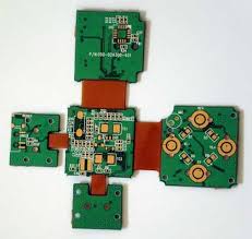
What Are the Common Types of Electric Circuit Boards Used in Electronics?
Another important consideration is the type of connection used to connect the various components on the circuit board. This can be accomplished through either through-hole or surface mount technology. Through-hole technology involves inserting lead components through pre-drilled holes on the circuit board and soldering them to pads on opposite sides of the board. Surface mount technology, on the other hand, places components directly onto the board’s surface.
If a circuit board is having problems, it’s important to identify the cause. Common problems include power supply issues, short circuits and open circuits. Power supply issues can cause excess current to flow where it shouldn’t, causing damage to components. An ohmmeter or continuity tester can be used to identify these issues. Short circuits and open circuits can be identified with a multimeter.
If you’re designing a new circuit, it’s a good idea to test it out on a breadboard before moving on to creating a physical prototype. These user-friendly tools offer a convenient way to experiment with your design and see real-time results without needing to solder or permanently etch the circuit board. Using these tools is especially helpful for beginners, as they can experiment with different circuits to find the best solution before committing to a permanent layout.